
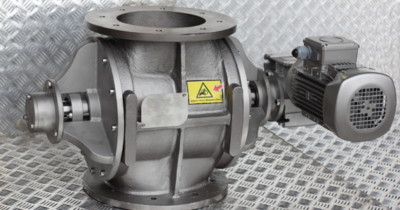
Controlled Feeding with Rotary Feeders
A rotary feeder is a rotary valve used for dosing. Since it releases approximately the same volume of product per revolution, the feed rate can easily be adjusted by changing the speed.
Capacity Adjustment via Speed
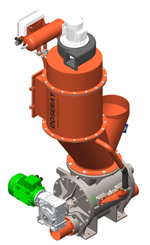
With a motor driven by a frequency inverter, the speed of the rotary feeder can be changed instantly to suit the process. This allows the same unit to be used for different products and capacities. For stable feeding, the hopper level and product flow, which affect pocket filling, are also kept under control.
Use with Weighing
Volumetric dosing can be inaccurate when the product density changes. Where greater accuracy is needed, the rotary feeder is operated together with a weigh hopper or a loss-in-weight system, and the weighing result automatically corrects the speed. See our dosing systems page.
What Is a Rotary Valve?
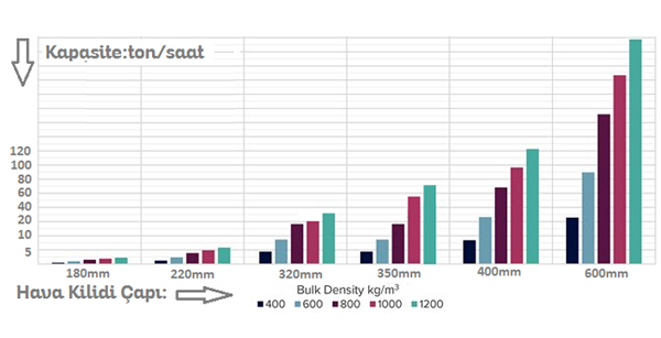
A rotary valve is a vaned mechanical device generally used in pneumatic transfer systems (pressure and vacuum) to separate powder or granular product from air. It is widely used beneath filters and cyclones in particular. The capacity of the unit is mainly determined by its diameter and rotational speed, while the vane tolerances are the most important factor determining its efficiency. A rotary valve can also be used as a dosing feeder and as a proportional discharger beneath silos.
To summarise the functions of a rotary valve briefly: it mixes the product with air and, using gravity, separates the product from the pressurised air. The vane design, tolerances and rotational speed of rotary valves vary with the type of process and the product used. Depending on the material, a rotary valve can also act as a crusher, or even work coupled with crushers. Rotary valves are manufactured in ST37 carbon steel, AISI 304 and AISI 316 stainless steel, Hardox and Ni-Hard. Bearing types and sealing elements (packing, mechanical seals, lip seals etc.) of the rotary valve (airlock) also vary with the process. Rotors can be supplied with blade tips, rounded pockets, adjustable vanes, scrapers or polyamide tips, among other options.
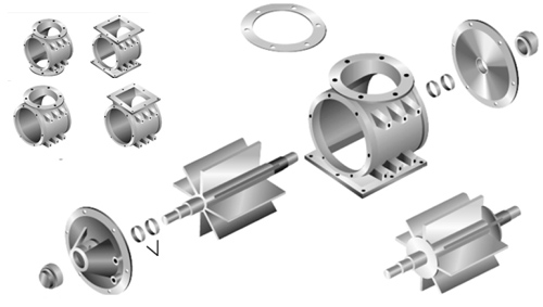
The images below give an idea of the rotor designs. Although the units look the same from the outside, their internal designs differ, which opens up many options when selecting a rotary valve. Process data must therefore always be taken into account when choosing a rotary valve. The most important point to remember is that not every rotary valve will work in every process.
Process-Specific Rotary Valves
Rotary Valve (Airlock, Rotary Feeder) Rotor Types
-

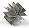
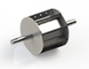
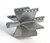
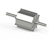
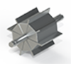
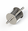
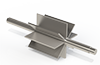
- A1-A2-A3: Open vanes
B1-B2-B3: Radiused (oval) vanes
C1-C2-C3: Adjustable and replaceable vanes
D1: Rotary valve with closed or adjustable rotor (dosing) -
Drop-Out Box and Eductor Solutions for Rotary Valves
In some processes a rotary valve is used within a pneumatic transfer system, but the direction of the pipe inlet and outlet can cause problems during maintenance, and dismantling pipes for maintenance is undesirable. In such plants, a standard rotary feeder is used instead of a blow-through rotary valve, and an adapter creating a venturi effect is fitted beneath it. This way, the connected lines do not need to be dismantled when servicing the rotary valve, giving you flexibility in the process. -
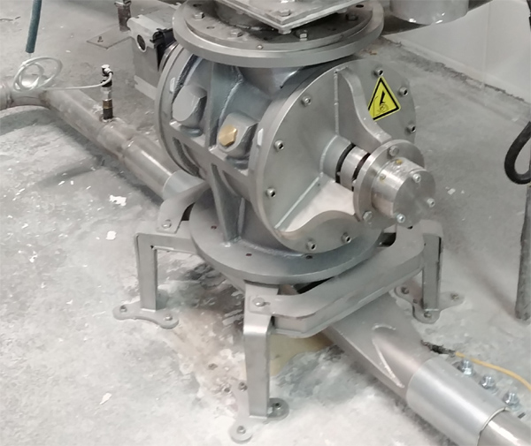

Wear-Resistant Rotary Valves
Wear-Resistant Rotary Valves and Airlocks
Rotary valves used in processes involving abrasive raw materials such as sand, ash, micronised calcite, dolomite, cement and quartz, particularly in the mining industry, must be built differently from their standard counterparts. These differences ensure that the process runs correctly and without interruption.
These differences fall under three headings:
1- Sealing elements (packing, lip seals etc.)
2- Wear-resistant housing design (lined or special alloy steel, Ni-Hard, carbide-type coatings)
3- Alloy steel rotors (Ni-Hard, Hardox, carbide-type coatings)
Internal design of the rotary valve: blow-through, standard and outboard-bearing rotary valves
There are other features that extend rotary valve service life, but these are the main ones that can be considered in general. Our rotary valves can be manufactured in all sizes with any of the optional features required.
In addition, if the system operates under pressure, this pressure puts the whole system under greater load and accelerates wear. The abrasive raw material mixed with air tries to escape through the sealing elements in particular; over time this first damages the seals, causing dust emissions, and then damages the housing and end covers.
To avoid the process described above and to extend this natural process in a controlled way, the right selection must be made. In abrasive processes like these, the equipment inevitably has a limited life. What matters is to avoid unplanned shutdowns: even if the rotary valve is damaged, it should keep running and, in plants operating 24/7, hold out until the next planned shutdown.
READ MORE Rotary Valve Catalogue