
How is a rotary valve used on spray dryers?
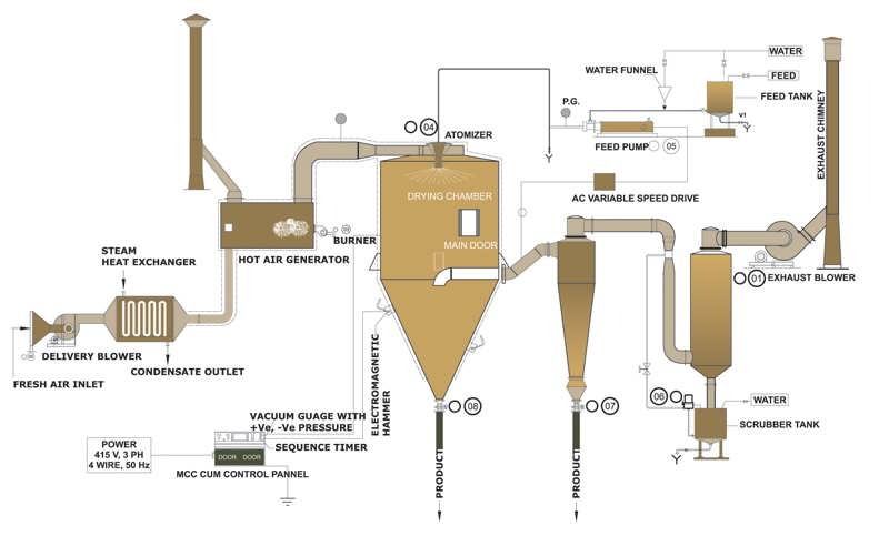
The rotary valve is generally used as a barrier between the outside environment and the spray dryer at the final stage of the drying process. The product descends by gravity from the 60–70 degree outlet cone into the rotary valve and is discharged. This may look simple, but it depends on a delicate balance, so much so that it even affects the agglomeration structure inside the spray dryer. Although it may look like an ordinary rotary valve at first glance, it is always important because it is the outlet element of the system. These system requirements can be summarised as follows:
1- Under vacuum, the rotary valve must not draw in more outside air than necessary.
2- If pneumatic conveying is to take place beneath the spray dryer, it must not allow upward air leakage that would upset the internal balance and increase caking of the product.
3- For high-sugar products that can change phase quickly, the design of the rotor and the inlet and outlet sections may change, and different coatings may be required.
4- For CIP cleaning, it must have a construction that is easy to dismantle, easy to maintain and washable.
5- The tolerances must suit the operating temperatures and parameters of the spray dryer. Otherwise, problems such as seizing or rubbing against the housing may occur at different temperatures.
Many more examples could be given, but this is essentially how rotary valves used under or at the outlet of a dryer should be approached. In addition to these features, the airlocks we build for spray dryers have further features not covered here. With many years of experience, we have the equipment and know-how this demanding selection requires.
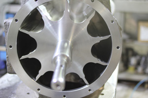
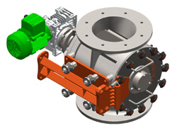
In the pictures beside and below, a special manhole has been fitted to the airlock under the dryer for easy cleaning. The process is washed down, especially when drying food products and products that cake easily (PST, etc.). The airlock does not need to be removed for thorough washing; once the safety requirements (position switch) are met, the manhole lets the operator easily carry out drying, cleaning and inspection. The vane design of a rotary valve used under a drying tower also varies with the type of powder passing through it. As mentioned above, the main differences are the number of vanes on the rotor, the vane type (radiused vanes) and the clearances.
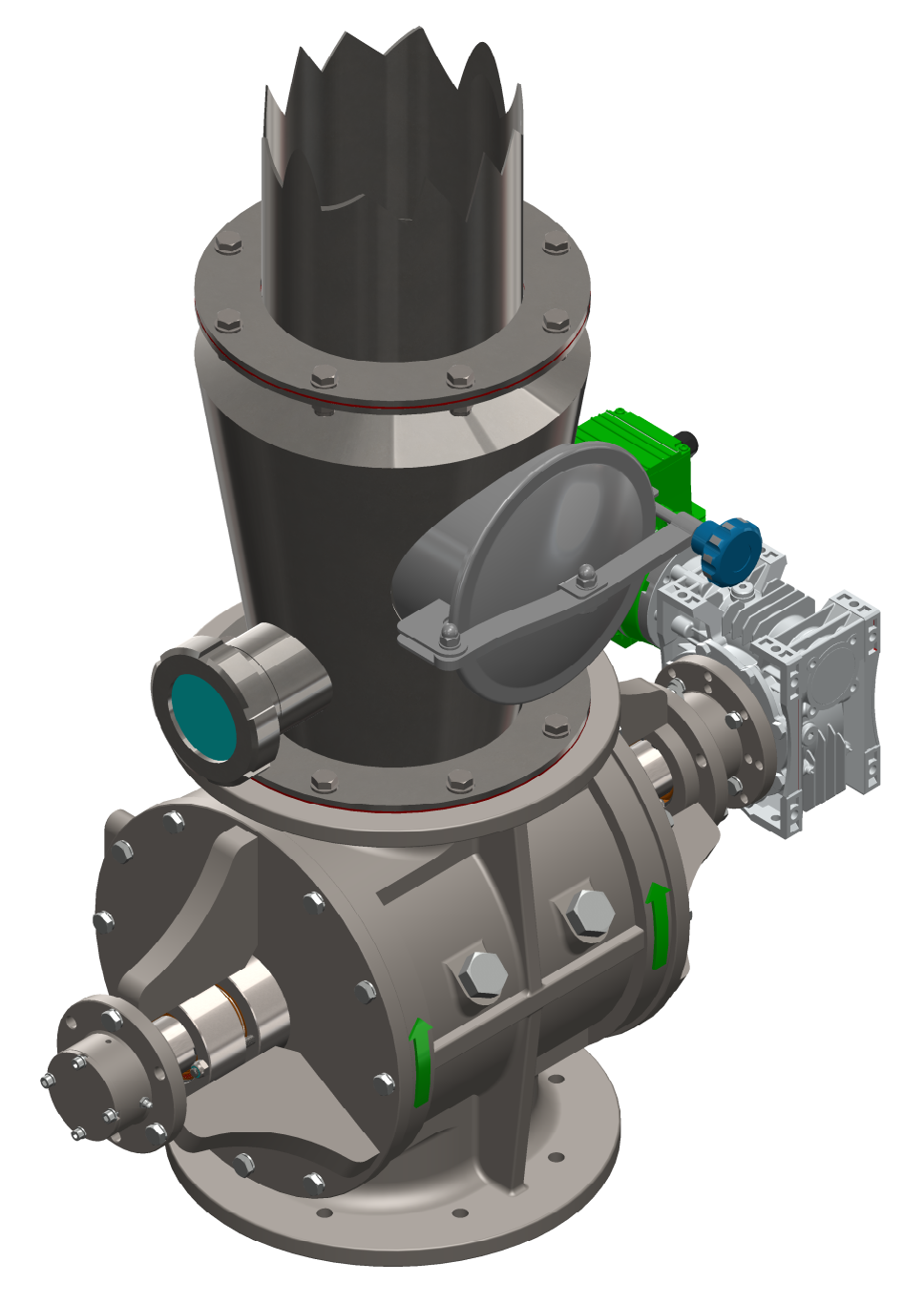
Rotary Valve (Airlock, Rotary Feeder) Rotor Types
-


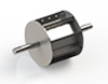
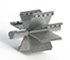
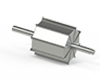
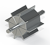
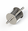
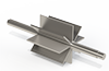
- A1-A2-A3: Open vanes
B1-B2-B3: Radiused (oval) vanes
C1-C2-C3: Adjustable and replaceable vanes
D1: Rotary valve with closed or adjustable rotor (dosing) - The pictures below show two different designs: radiused vanes and vanes with angled tips. This alone shows how many variants exist within the same process.
-

-
Spray dryer design and airlocks
-
Special airlocks for drying
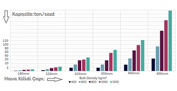
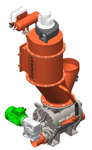
Conveying airlocks and rotary valves for dryer outlets
Our rotary airlocks can be built in every diameter we manufacture, with any optional features required.
In addition to all the points above, if there is a conveying system under the dryer, the sealing elements must be selected specifically for the product. This is what sets airlocks for spray dryers apart from standard products. Another factor is temperature: heated metal expands and grows. Clearances are therefore critical in spray dryers operating at high temperatures. High-sugar raw materials such as milk powder, PST and fruit extracts are prime examples.
READ MORE Rotary Valve Catalogue