
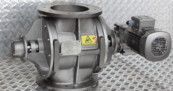
ATEX Airlock
On lines conveying combustible dusts such as sugar, flour, starch, sulphur or plastic powder, the rotary valve is one of the points with the highest explosion risk: the rotating rotor runs with a very small clearance to the housing, and incorrectly selected equipment can become an ignition source through friction or static electricity.
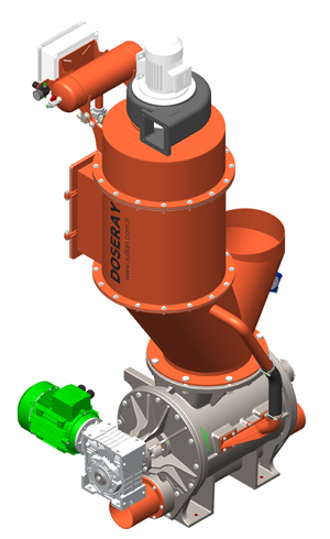
DOSERAY ATEX rotary valves are designed according to the classification of the area in which they are installed (Zone 20, 21 or 22 for dust). The rotor-to-housing clearance, bearing and seal design, and motor and gearbox selection are determined according to this classification; earthing of the housing and rotor against static electricity is taken into account in the design. If required, a rotor motion sensor sends a signal to the automation system the moment the rotary valve stops.
The housing material is selected according to the nature of the product: ST37 carbon steel, AISI 304 or AISI 316 stainless steel; Hardox or Ni-Hard options are used for abrasive dusts.
What Is a Rotary Valve and Where Is It Used?

For ATEX applications we manufacture both standard (drop-through) rotary valves used under filters and cyclones and blow-through airlocks connected directly to the pneumatic line.
-

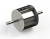
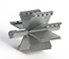
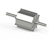
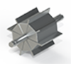
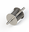
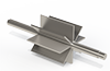
- A1-A2-A3: Open vanes
B1-B2-B3: Radiused-oval vanes
C1-C2-C3: Adjustable and replaceable vanes
D1: Rotary valve with closed or adjustable rotor (dosing) -
Eductor for Rotary Valves
Although in some processes the rotary valve is used within the pneumatic conveying system, the pipe inlet and outlet directions can cause problems during maintenance; dismantling the pipes for maintenance is undesirable. In such plants, instead of a blow-through rotary valve (airlock), a standard rotary feeder can be used with a venturi-effect device fitted underneath. This way the connected lines do not have to be dismantled when servicing the rotary valve, giving the process greater flexibility. -
-
What Is Air Leakage in Rotary Valves and How Does It Affect the System?
This topic often leads to misunderstandings and incorrect use. It should be remembered that every rotary valve needs a running clearance in order to rotate, which means there is a gap between the housing and the rotor. On leaving the factory, this clearance is generally set to 0.15–0.30 mm on all rotary valves. If the system performs pneumatic conveying and the conveyed material is somewhat abrasive, this clearance can increase over time. Increased clearances can lead to air leaking upwards through the rotary valve (blow-back) and to bridging problems.
- To prevent such situations, the leakage air must be vented, especially in blow-through rotary valves. If venting is done correctly, rotary valves can operate without problems with wear up to a clearance of 1 mm. That is why venting of the leakage air and the orientation of the rotary valve are important on all pneumatic conveying lines. Otherwise, performance problems arise in the system even with very slight wear.
-
- In processes where wear is expected, the vane thickness of the rotary valve, high-alloy steel vanes, end covers, rotor speed and venting of the leakage air are important. Product selection therefore needs careful attention from the very beginning.
.
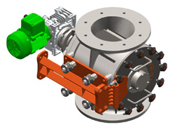

Rotary Valve Technical Dimensions
The flange and connection dimensions of the ATEX models are identical to our standard series, so a rotary valve on an existing line can be replaced with an ATEX model without modifying the installation.
Standard Rotary Valve Models
All of the models below can be ordered as ATEX versions with certified motors and sealing elements.
Rotary Valve Capacity Table
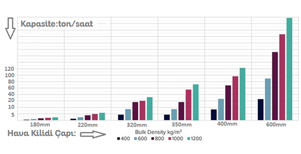

The values in the table show the theoretical volume conveyed per revolution. Since the rotor in ATEX applications is usually run at a lower speed, we recommend calculating the actual capacity together, based on your product's bulk density and fill ratio.
READ MORE Rotary Valve Catalogue